Introduction | Section A(1-10) | Section A(11-16) | Section B | Section C | Section D | Section E | Section F | Section G
Download AutoCAD DWG files (zip archive): Section A | Section B | Section C |
Sections D-G
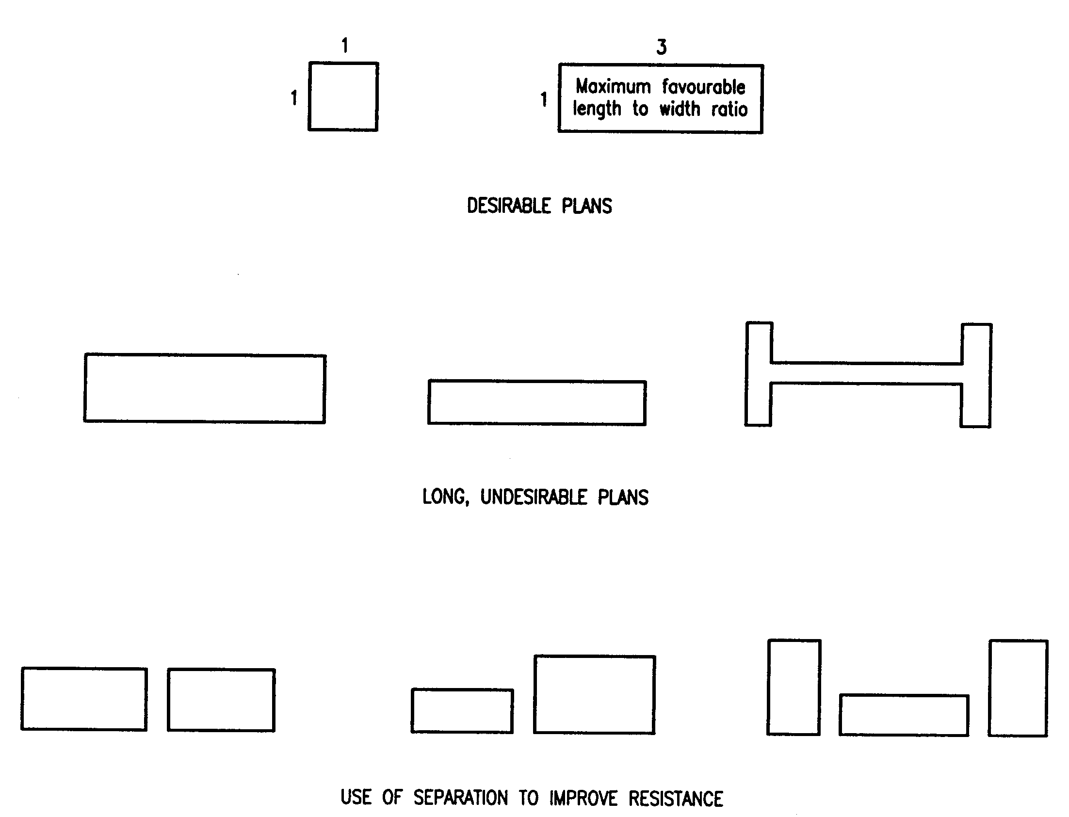
Figure A-1: Plan Shapes of Buildings
The success with which a building survives an earthquake is significantly affected by its shape in plan. Most buildings with a simple rectangular shape, with no projections, perform well under earthquake conditions, provided the construction is adequate. Long narrow buildings should be avoided. Long buildings should be divided into separate blocks with adequate separation.
Figure A-2: Size and Location of Wall Openings
The location and size of openings in walls have a significant effect upon the strength of a wall and its ability to resist earthquake forces. Openings are to be located away from a corner by a clear distance of at least ¼ of the height of the opening. It is recommended that a minimum distance be 15". The total length of the openings should not exceed ½ the length of the wall between consecutive cross walls. The horizontal distance between two openings should not be less than ½ the height of the shorter openings.
Figure A-3: Typical Wall Corner Detail
Figure A-4: Typical Wall Junction Detail
Figure A-5: Reinforced Masonry Gable Arrangement
An important factor contributing to the earthquake resistance of concrete masonry buildings is the detailing and placing of steel reinforcement. The reinforcing guides given in these figures are only to be used for simple single storey buildings constructed of good quality concrete blocks. In addition to the minimum vertical wall reinforcement, all walls, corners and junctions are to be reinforced. All vertical reinforcement is to be securely fixed to the ring beam. Horizontal reinforcement must be placed every 3 courses. Window and door jambs should be reinforced and tied into the lintels. Gable walls are to be reinforced by bars fixed to the concrete beam at eaves height and to the sloping ring beam at the top of the gable.
Figure A-6: Recommended Method for Construction on Sloping Sites
Buildings sited in exposed areas (e.g. on the brow of a hill) are most vulnerable, while those sheltered by natural topography are less vulnerable. In siting the building, therefore, steep slopes and edges of cliffs should be avoided, as well as other conditions such as steep sided valleys where exceptionally high wind speeds are found.
Where building on a steep site is unavoidable, reinforced concrete tie beams should be constructed to reduce the untied height of the columns to a maximum of 10 feet, as shown. On more gently sloping sites, a satisfactory suspended slab may be achieved through the use of loosely compacted granular fill as permanent formwork.
Figure A-7: Hip Roof Construction
Figure A-8: Gable Roof Construction
Figure A-9: Rafter/Ring Beam Connection
Figure A-10: Wall Plate Connection and Hurricane Straps' Details
Experience and research have shown that flat roofs are vulnerable to high winds. In an effort to reduce the uplifting wind forces on the roof, the roof pitch should be not less than 25 to 30 degrees. Hip roofs should be used, since this shape of roof has been found to be more hurricane resistant than the gable of roof. Where gable roofs are used they should be strongly constructed. Roof overhangs also experience high local pressures and, where possible, these should be kept to a minimum or removed completely. Where buildings have roofed patios or verandas, their roofs should be separate structures rather than extensions of the main building roof, so that the patio or verandah roof may be lost without endangering the safety of the main roof. The main roof must be securely fixed to the ring beam and ridge beams. This may be achieved by the use of hurricane straps.
Introduction | Section A(1-10) | Section A(11-16) | Section B | Section C | Section D | Section E | Section F | Section G
| USAID/OAS Post-Georges Disaster Mitigation: http://www.oas.org/pgdm | Page last updated on 17 Sep 2001 |