|
The IP protocol identifies each computer connected
to the network by its corresponding address. This
address is a 32 bits number in Ipv4, that has to be
unique for each server or computer, which we will
call “host”. The IP addresses are usually
represented as four decimal ciphers, of 8 bits each,
separated by dots.
The Internet address (IP Address) is used to
identify both the host and the network to which it
belongs, in a way that distinguishing the hosts
connected to the same network, is possible. With
this purpose, and considering that there are
different sizes networks connected in Internet, five
kinds of different addresses have been settled.
The idea is that according the network's topology,
more bits are used for the network’s address than
for the host’s address, or viceversa. Figure I-8
shows the three kinds of addresses, A,B and C, to
which we added type D and E to represent all the
receptors (“multicast”) and for future purpose.
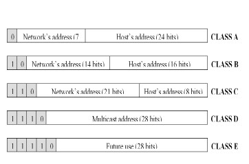
Figure I. IP address’s kind schema.
The first bits (shaded) define the kind of address
that the next bits carry. As a reference, with 8
bits (each part between dots), you can have 256
different values (from 00000000=0 to 11111111=255).
For example, an IP address would be 192.228.17.57 (
in bits
11000000 11100100 00010001 00111001),
representing a C kind address.
Let us see the most important characteristics of
each kind:
- Class
A:
Are those that in their first 8 bits have a fixed
bit
0 (indicating class A) and 7 variable bits.
That is, they can differentiate from
00000000=0 to
0111111=127. Nevertheless, the 0 and the 127
are reserved, so there might be only126 potential
addresses class A that correspond to the first byte
of the address (the first number before the dot).
The other three bytes (24 bites) are available for
each one of the hosts belonging to the same network.
This means that there might exist 224 =
16.387.064 computers or servers in each network of
this kind. This kind of addresses is used in very
extensive networks, but we must keep in mind that
there can be only 126 networks of this size. That is
why big commercial networks use them, although that
there are few organizations that get a “class A”
address. Generally big organizations use one or more
“class B” networks.
- Class
B:
These addresses use in their first byte the
10 bits fixed (indicating class B) and with
the rest of the first byte’s bits admits addresses
from 128=10000000
and 191=1011111,
including both. In this case, the network’s
identifier is obtained from the first two bytes (16
bits – 2 bits already used = 14 bits) of the
address, having to be a value between 128.1 and
191.254 (it is not possible to use values 0 and 255
because they have a special meaning). Therefore,
there will be 214 = 16.384 different
networks class B. The last two bytes of the address
constitute the host’s identifier allowing a
maximum of 216 = 64.516 computers in the
same network. Addresses of this kind should be
enough for most of the big organizations. In case
the number of computers needed is bigger, it would
be possible to have more than one “class B” address,
avoiding so the use of a “class A” one.
- Class
C:
In this case the value of the first byte will
include the
110 bits fixed (indicating class C) and then
the first byte must be between 192=11000000
and 223=11011111,
including both values. This third kind of address
use the three first bytes for the network’s number,
with a range that goes from 192.1.1 up to
223.254.254. Therefore, there will be 221
= 2.097.152 different networks class C. So, we have
one byte (8 bits) free for the host, allowing
a maximum of 254 computers connected to each
network, since 28 =256 but the 0 and the
255 are not used.
- Class
D:
The addresses that begin with the
1110 bits fixed followed with the “multicast”
address that is for every destiny, are usually
called class D.
- Class
E:
We usually call class E the addresses kept for
future use.
Table I resumes the important characteristics of
class A, B and C addresses.
Internet’s IP addresses table.
|
|
Class |
First byte |
Network’s identification |
Host’s identification |
Networks number |
Hosts number |
|
A |
1 .. 126 |
1 byte |
3 byte |
126 |
16.387.064 |
|
B |
128 .. 191 |
2 byte |
2 byte |
16.256 |
64.516 |
|
C |
192 .. 223 |
3 byte |
1 byte |
2.064.512 |
254 |
Table I. IP addresses classes.
It is important to notice
that the values 0 and 255 in any address’s byte can
not be used normally because they have other
specific tasks.
The number 0 is set apart for machines that do not
know their address. It can be used either in the
network’s identification in machines that still not
know the network’s number to which they are
connected. Or in the host’s identification
for machines that do not know their host
number in the network; or in both situations.
As
we have seen, number 255, is reserved for the
multicast. This is necessary when we want a message
to be visible by every system connected to the same
network. This might be useful if we need to send the
same packet to a specific number of systems,
resulting more efficient than sending the wanted
information individually to each one. Another
situation for the use of multicast is when you want
to change the computer’s domain name for its
corresponding IP number and you do not know the
closest address server’s name
Usually, when the use of multicast is required, we
use an address made of the ordinary network’s
identifier and the number 255 (all ones in binary)
in each byte that identifies the host.
Nevertheless, due to convenience it is also allowed
the use of the number 255.255.255.255 for the same
purpose, so it is easier to refer to every network’s
systems.
Subnets
In
some extensive organizations it might arise the need
to divide the network into smaller ones (subnets).
Then, bits fixed for the host’s addresses in each
class, are divided into two groups. Part of them
defines the subnet, and the rest the computer inside
the subnet. It is necessary to consider that for the
external world (that handles the network’s addresses
only) this decision of the local network, or
computer’s group, is not relevant. Then, each subnet
can manage its host’s address bits as it wishes.
The
division of the host address bits into subnets is
done through a “mask”, which is a well defined bits
standard that determines which bits to use in the
network’s identification, and which ones identify
the computer within the subnet.
For example, let us consider the following values
for a class C address:
IP
address: 192.228.15.57 In bits:
1100000.11100100.00010001.00111001
Mask:
255.255.255.22 In bits:
1111111.11111111.11111111.11100000
Logic AND : 192.228.17.32 In
bits:
1100000.11100100.00010001.00100000
That is to say, that from the last 8 bits, for the
host’s address in class C, the first 3 bits (in
blue) determine the subnet; and the last 5 (in
yellow) masks (bring to 0) the computer’s address
within the subnet. The binary value of the original
last 5 bits will determine the computer’s address
within the subnet. In this example, the address
192.228.15.57 determines the class C network
192.228.15, and inside this one the subnet number 1=
001 and in the subnet 1, the computer 25=11001.
Figure 2 shows an example with 3 subnets, LAN X,
LAN Y and LAN Z, following up the class C case seen
above. The set is seen for the rest of Internet as
the address 192.228.17.x, where x represents the
class C host’s address.

Figure 2. Subnets.
ROUTES
DETERMINATION
It is clear that an important part of the
protocol's performance depends on the way the routes
that the packets will follow, are determined. We use
algorithms that work with different sorts of values
to determine the route, and we call them “metrics”.
These metrics, either automatically calculated or
defined by the network’s manager, are used to make
and adapt the tables used by the routers and
intermediate nodes. The most common metrics are:
-
Path’s Length:
It is the most used metric. Sometimes, costs are
assigned to each way’s section, then the path’s
length is the sum of each jump’s cost. In other
cases the length is calculated as the sum of the
jumps the packet has to undertake.
-
Reliability:
It is an arbitrary value assigned by the network’s
manager. In some case it reveals the Bits Error Rate
of the section. In other cases is the probability
that the link fall down, the recovery ability or a
combination of both.
-
Delay:
Represents the time needed to transport a packet
from one point to another. This value depends on
many factors: section’s bandwidth, distance to be
covered, queues made in the routers, link’s
congestion, etc. This metric is generally one of the
most useful.
-
Bandwidth:
It is measure of the information’s transmission
speed expected in a link. Generally, the higher the
better, even though all by itself it is not a
definitive metric. For example, we have to take into
account factors like the queues in the routers, etc,
which make that the link’s speed is wasted.
-
Load:
Indicates how busy an element in the network, (like
a router), is. For example, the processor’s usage
percentage is a factor that influences this metric,
determining the process capability in packets per
second.
-
Cost:
It refers to the monetary cost. In some cases it is
better to route a packet by a longer but cheaper
route.
Roberto Rossi
Universidad Blas Pascal
|