|
Background:
Non Ionizing Radiation
Monitoring systems are employed as a part of management risk
information system used by national regulators in order to promote
conscious awareness on the subject and attenuate people concerns on
this matter.
There are several
systems available from different manufactures to perform such
measurements, being the different choices based on the local demands
and also the economical and social conditions.
In Brazil, NIR
exposure limits for Radio Frequency emitters are defined by the
National Telecommunications Agency ANATEL, according to OMC and
ICNIRP standards. ANATEL also perform regular measurements following
an annual regulatory enforcement plan and in response to specific
demands, collect from different sources, such as call center, web
services and other standard public relations channels.
Information:
As an effort to
increase the information about NIR levels in Brazil, ANATEL, which
already operates 12 broadband isotropic probes for electric and
magnetic field, and 30 narrowband isotropic probes for electric field,
considered in 2007 the implementation of an automated NIR monitoring
network, taking into consideration the following principles:
-
The measuring
system must be able to run measures in all relevant frequency bands
including radio and TV broadcasting in the 500 kHz up to 800 MHz
range, mobile communications bands and other services up to 2,7 GHz
frequency bands.
-
The measuring
system must be able to measure electrical fields from as low as 0,8
V/m, defined at about 3% of the lower general public exposure limit,
up to 61 V/m, defined as 100% of the lower occupational exposure
limit. Values bellow this range might severely limit the
manufactures competition on a bidding process without adding
relevant capability for the measurement system, while values above
this range will also be non practical for any application, since
higher limits would demand immediate action to reduce the emission
levels and further analysis of the specific causes, using a narrow
band probe to isolate the contribution form different emitters.
-
The measuring
system must be able to work without any human interference for long
periods, up to 14 days and keep these data in its memory.
-
The measuring
system must be able to transmit collected data using mobile network.
-
The system must be
equipped with GPS, been able to operate mounted on a vehicle,
allowing simple measurements to be performed in movement along a
route, in the same fashion as drive tests. Such large area overview
are useful to confirm possible hot spots, produce large volumes of
data with low human cost, provide a safe environment to operate
the equipment, even when no agreement can be achieved for a fixed
installation.
-
The measuring
system must have its own power supply in order to operate at least
two hours without any external power supply. And with external power
supply system must operate in continuous way.
-
The measuring
system must have an anti-thief module and must be able to operate in
open areas without any special environmental protection.
-
All these
specifications for measuring system must be compatible with software
system in development inside ANATEL, recording complete statistical
data from all measurements, including time stamp, average and
standard deviation for the level and geographic coordinate
measurements, maximum EF measurement, number of measurements and
duration of each record, plus relevant error detected during
measurements that might compromise the presented results.
In order to achieve
these requirements ANATEL published a tender process at the end of
2007, asking for manufacturers to provide 52 measuring systems. The
project winner was SALTECH (www.saltech.com.br),
a Brazilian industry in a technological partnership with CPqD
Foundation (www.cpqd.com.br),
a Brazilian research and development center for telecom. CPqD already
have developed a NIR system, CPqD Monitoração RNI (CPqD NIR Monitoring),
which was presented in last CITEL meeting at San Salvador.
The measuring system
unit is called Unidade Remota de Coleta e Armazenamento URCA, which
means Collect and Storing Remote Unit for electrical field.
This unit is composed
by an isotropic electrical field sensor constructed with three axes
short dipoles with Schottky diodes with high impedance lines in the
frequency band between 300 kHz and 3 GHz.
Micro controlled and
with an internal GPS module to provide geographical and time stamp
data together with electrical field measurements, the unit,
automatically, will provide all registries during its operation. For
remote operation, there is a modem connection for use with mobile
networks allowing operation in GSM and CDMA technologies. Your battery
system provides system operation during at least two hours without
external power, AC (110 240 V) or DC (12V). There is an adapter for
DC power supply for use in cars or vans allowing continuous colleting
data during car driving.
The Figure 1 shows URCA with a notebook for programming its
collecting functions, like time, space and delay between measurements.
In the notebook screen is possible to see actual electrical field
intensity value and a graphical with the values collected.
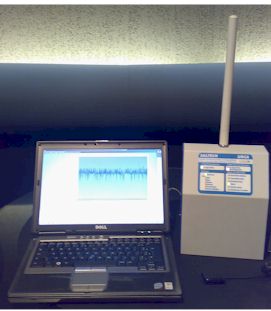
Figure
1 URCA and a notebook for
programming
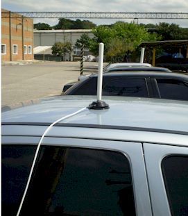
The Figure 2 and Figure 3 show some kind of URCA mounting for data logging,
in a car for mobile measurements and in a fixed point.
Figure
2
URCA mounting on car

Figure 3
Fixed URCA mounting
The Table 1 shows probe characteristics and Table 2 shows URCA unit
general specification.
|
Probe |
|
Frequency Band |
300 kHz up to 3 GHz |
|
E Field Detector |
Schotky diodes |
|
Directivity |
Three axes - Isotropic |
|
Frequency Response
(without correction factor) |
- 3,7 dB (300 kHz 750 kHz)
1,5 dB (750 kHz 2,0 GHz)
3 dB (2,0 GHz 3,0 GHz) |
|
Dynamic Range |
0,8 90 V/m |
|
Linearity |
5,5 dB (0,8 1,3 V/m)
3,7 dB (1,3 up to 3,0 V/m)
1,5 dB (3,0 up to 8,0 V/m)
0,5 dB (8,0 up to 65,0 V/m) |
|
Isotropic response |
± 0.6 dB |
|
Calibration |
Calibration Laboratory from CPqD |
|
Data rate |
1 to 3 samples per second |
|
Probe diameter |
18 mm |
|
Probe length |
300 mm |
Table 1 E-Field Probe General
Specification
|
URCA |
|
Measuring Units |
mW/cm2, W/m2, V/m,
% (do limite de referência) |
|
Power Supply |
110/220 V AC and 12 V DC |
|
Geographical Positioning |
GPS -12 channels Compatible with WAAS/EGNOS |
|
Positioning Data |
Latitude (Lat)/Longitude (Long) in grades, minutes, seconds e
and tenth of seconds) |
|
Geodesical system |
WGS 84 |
|
Positioning accuracy |
< 5 m (DGPS, WAAS)
< 10 m |
|
Data logging |
Up to 3600 results (including E-field intensity and time stamp) |
|
Data Transmission |
Modem GSM / CDMA using switched circuit via RS 232
interface |
|
Data Logging Modes |
Time
average: one average value computed over a period of X
minutes. This mode shall be used for the classical time
averaging for fixed installations.
Time
average with pause: one average computed over a period of
X minutes, with pauses between subsequent measurements that
last Y minutes. This mode shall be used for the classical time
averaging for fixed installations, but where the operator
wants to extend the operational capability of the system,
reducing the amount of measurements performed during a long
period.
Spatial
average: one average value computed over an area of Z
meters (radius). This mode shall be used for the classical
spatial averaging for mobile installations, or simply to
reduce the number of measurements to a relevant area.
Segmented
Spatial average: one average value computed over an area
of Z meters (radius), pausing all measurements for an adjacent
area of additional defined by a radius of K meters.. This mode
shall be used for the classical spatial averaging for mobile
installations, but where the operator wants to extend the
operational capability of the system, reducing the amount of
measurements performed over an extended route.
Spatial and
time average: one average value computed over an area of Z
meters (radius), with maximum duration of X minutes. This mode
combines the techniques of spatial and time averaging into a
single procedure.
Spatial and
time delayed average: one average value computed over an
area of Z meters (radius), with maximum duration of X minutes,
pausing for Y minutes after each complete measurement.
Segmented
Spatial and time delayed average: one average value
computed over an area of Z meters (radius), pausing all
measurements for an adjacent area of additional defined by a
radius of K meters, with a maximum duration of X minutes,
pausing for Y minutes after each complete measurement. |
Table 2
URCA general Specification
This system will
be in operation on third quarter of 2008, been expected to have
the actual measurement results from measurement campaigns
performed by ANATEL publicized by
the beginning of 2009.
National Telecommunications
Agency
ANATEL
|
Additional Information: Document published as
CCP.II-RADIO/doc. 1623/08.
|
|

 New brazilian Non
Ionizing Radiation
New brazilian Non
Ionizing Radiation