Caribbean Disaster
Mitigation Project
Implemented by the Organization of American States
Unit of Sustainable Development and Environment
for the USAID Office of Foreign Disaster Assistance and the Caribbean Regional Program


Caribbean Disaster
Mitigation Project |
|
2.0 Natural Hazards Affecting St. Lucia
3.0 Lucelec Design and Construction Standards
4.0 Vulnerability of Existing Facilities
5.0 Programme for the Remainder of the Project
The primary natural hazards facing islands in the Caribbean are:
In the case of St Lucia, volcanic activity is an important consideration but falls outside the present work. The other five items are discussed generally below.
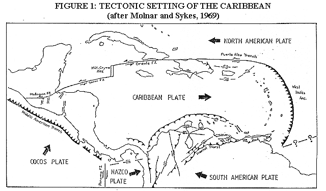
Seismic events in the Eastern Caribbean, where St Lucia is located, are principally associated with a subduction zone at the junction of the Caribbean Plate and the Americas Plate. The Caribbean Plate is moving eastward relative to the Americas Plate at a rate of about 2Omm per year. The Americas Plate dips from east to west beneath the Caribbean Plate along a north-south line approximately 150km east of St Lucia. This leads to a moderate level of inter-plate seismicity in the vicinity of St Lucia. The maximum historical intensities of earthquakes in St Lucia as reported by Dr John Shepherd (formerly of the Seismic Research Unit, UWI, Trinidad) are VII and VIII on the Modified Mercalli Scale. The Caribbean Uniform Building Code (CUBiC) recommends a Z-factor of 0.75 for St Lucia. However, a 1983 study by Faccioli, Taylor and Shepherd recommends a Z-factor of 0.5 and a design ground acceleration of less than or equal to 0.1g. This places St Lucia somewhere between zones 2 and 3 of the UBC and the (old) SEAOC codes of the USA. In other words, the level of seismicity in St Lucia is moderate but sufficiently important not to be ignored.
Figures 1, 2 and 3 (at the end of this sub-section) show the tectonic setting of the Caribbean, the main physical features of the Eastern Caribbean and a cross section through the island arc.
The two most recent earthquakes to have caused significant damage in St Lucia are:
| 19th March 1953 | Richter magnitude 7.5, Modified Mercalli intensity VII in St Lucia; |
| 16th February 1906 | Richter magnitude 7.0, Medvedev-Sponheuer--Karnik (MSK) intensity VII-VIII in St Lucia. |
An isoseismic map of this latter event is reproduced in figure 4c (at the end of this sub-section).
The catastrophic Guadeloupe earthquake of 8th February 1843 produced a Medvedev-Sponheuer-Karnik (MSK) intensity of VII in St Lucia. An isoseismic map of that event is reproduced in figure 4b (also at the end of this sub-section). Other isoseismic maps (figures 4a and 4d) are presented for the events of 11th January 1839 (Richter M=7.5-7.8, MSK=VIII) and 21st May 1946 (Richter M=7.0, MSK=VII).


St Lucia lies in the North Atlantic Ocean, one of the six main tropical areas of the earth where hurricanes may develop every year. In its April 1991 Information Bulletin, the Caribbean Cyclone-Resistant Housing Project (CCRHP-UWI) states that over 4000 tropical storms have occurred in the region within the past 500 years, half of which developed into hurricanes. A general historical record of those hurricanes affecting St Lucia from the seventeenth century to 1980 is given in Table 1 (at the end of this sub-section).
Cyclones are formed when an organised system of revolving winds, clockwise in the Southern Hemisphere and anti-clockwise in the Northern Hemisphere, develop over tropical waters. The classification of a cyclone is based on the average speed of the wind near the centre of the system. In the North Atlantic they are called tropical depressions for wind speeds up to 17 metres per second (m/s). Tropical storms have wind speeds in the range 18 m/s to 32 m/s. When the wind speeds exceed 32 m/s the system is called a hurricane.
A hurricane is a large-scale, low-pressure weather system. It derives its energy from the latent heat of condensation of water vapour over warn tropical seas. In order to develop, a hurricane requires a sea temperature of at least 260C which must be maintained for several days for the system to sustain itself. A large expanse of sea surface is required for the formation of a hurricane, about 400 kilometers (km) in diameter. A mature hurricane may have a diameter anywhere from 150. km to 1000 km with sustained wind speeds often exceeding 52 m/s near the centre with still higher gusts.
A unique feature of a hurricane is the eye. The system of revolving winds does not converge to a point, but becomes tangential to the wall of the eye at a radius of 8 to 12 km from the geometric centre of the disturbance. The eye is an area of light winds, thin cloud cover and the lowest barometric pressure. The eye provides a convenient frame of reference for the system and can be tracked with radar, aircraft or satellite. Figure 5 (at the end of this sub-section) shows the variations of wind speed and barometric pressure with distance from the eye of the hurricane.
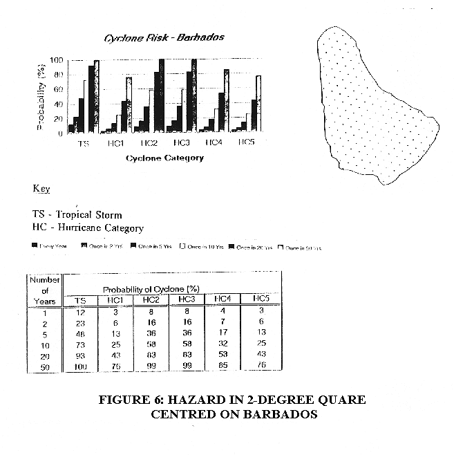
In Figure 6 (at the end of this sub-section) a probability chart and table (CCRHP-UWI) are presented depicting the cyclone hazard in a 2-degree square (approximately 220 km x 220 km) centred on Barbados. The statistics for St Lucia are not readily available but are likely to be very similar to those for Barbados. It is estimated that the probability of a direct hit on St Lucia is about 65% of the probability of a passage through the 2-degree square as shown on figure 6.
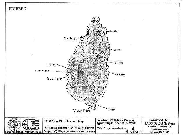
As part of the OAS Caribbean Disaster Mitigation Project wind hazard maps have been produced by TAOS Output System. (A full description of this system is provided in the paper "The Arbiter Of Storms: A High Resolution, GIS Based System for Integrated Storm Hazard Modelling" by Charles C. Watson, Jr. The 100-year Wind Hazard Map for St Lucia is reproduced as figure 7 in this report. It shows the influence of topography on the wind speed.
The destructive potential of a hurricane is significant due to high wind speeds, potential torrential rains which produce flooding and occasional storm surges with heights of several metres above normal sea level.
The Saffir-Simpson scale is often used to categorize hurricanes based on wind speed and damage potential. The following five categories of hurricanes are recognized:
| Wind Speed | |||
| Category | m/s | mph | Damage |
| HC1 | 33 - 42 | 74 - 95 | Minimal |
| HC2 | 43 - 49 | 96 - 110 | Moderate |
| HC3 | 50 - 58 | 111 - 130 | Extensive |
| HC4 | 59 - 69 | 131 - 155 | Extreme |
| HC5 | >69 | >155 | Catastrophic |
The Caribbean Uniform Building Code and the BNSIINCST/OAS/BAPE Wind Code set out the basic wind parameters for the design of buildings in St Lucia. The normal requirement is the 1-in-SO-year wind, ie a wind speed which on average is not expected to be exceeded more than once in 50 years. In St Lucia this produces a basic 3-second gust wind speed of 58 m/s. This represents a category 3 hurricane. For a category 4 hurricane, a wind speed is experienced which on average is not expected to be exceeded more than once in 100 years. The 1-in-200-year wind is experienced in a category 5 hurricane.
October 23 or 24, 1694
June 12-14,1780
October 10-18, 1780 - "Great Hurricane"
October 23, 1817
October 21, 1818
September 21-22, 1819
October 13-15, 1819
July 9, 1837
October 6, 1841
September 2-5, 1951
October 30 - November 6, 1956 - heavy swells from "Greta" to west-northwest
July 10, 1960 - "Abby" - destruction most severe in memory
September 25, 1963 - "Edith" - $3,465,000 in damages
September 5-22, 1967 - "Beulah" - torrential rains; $3 million in damages
August 4, 1980 - Hurricane "Allen"

Although hurricanes are often accompanied by heavy rains, severe rainfall events resulting in flooding in St Lucia are also, and frequently, associated with troughs and tropical depressions. The risk of flooding is therefore not restricted to, nor more likely to occur, during hurricane events.
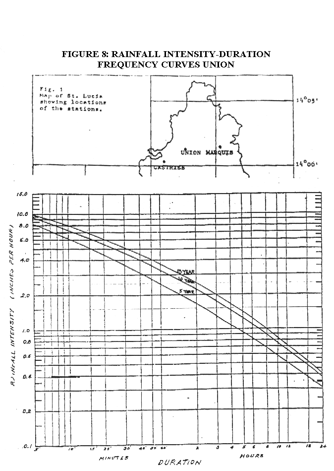
Drainage systems and structures in St Lucia are generally designed for rainfall events having return periods of 20 years. This means that such systems are likely to become overloaded and cause some degree of flooding when rainstorms are experienced with return periods greater than 20 years. Figure 8 and 9 (at the end of this sub-section) show the rainfall intensity-duration-frequency curves for two locations in St Lucia.
Generally, lower lying areas will be more susceptible to flooding than higher and sloping ground.
The damage caused by flooding depends on the type and elevation of facilities in the location. The results of flooding may range from the inconvenience of temporarily submerged driveways to the loss of equipment and finishes inside flooded buildings and consequential disruption of the functions.

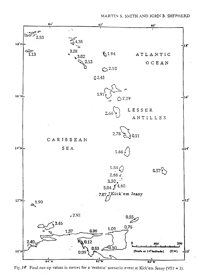
Tsunamis (sometimes colloquially called tidal waves) are usually caused by tectonic earthquakes and volcanic eruptions. Landslides and underwater explosions have also been known to cause tsunamis. There are few historical records of tsunamis in the Caribbean. However, recent studies by Martin Smith and John Shepherd have identified future eruptions of the Kick 'em Jenny volcano as a potential tsunami hazard to St Lucia. The travel time would be about 30 minutes from eruption at source to Castries and the final run-up value on the St Lucia west coast would be about 1.8 metres for a realistic scenario. The 1755 Lisbon earthquake produced tsunami waves in Barbados and, probably, in St Lucia as well. Such an event, with a return period of a few hundred years, could produce tsunami waves on St Lucia's east coast of between 2 and 5 metres. Figure 10 at the end of this section shows the tsunami hazard in the Eastern Caribbean.
Storm surges are associated with hurricanes and consist of unusual volumes of water flowing onto shorelines. Such surges have been responsible for much of the damage caused by hurricanes, especially in large, low-lying coastal settlements.
Storm surges are complex phenomena which behave quite differently from one shoreline to another. The several main components governing their behaviour are:
| Astronomical Tide: | water levels due to tidal variation; |
| Initial Water Level: | elevated basin-wide water levels cause4 by larger storms; |
| Pressure Deficit: | elevated water levels caused by low pressure Systems; |
| Inland Runoff: | raised water levels in rivers and sea outfalls due to prolonged rainfall; |
| Current Surge: | ocean currents caused by high winds leading to the "piling up" of shallow waters; |
| Wave Setup: | water accumulating from continuous trains of waves on breaking on shoreline; |
| Wave Action & Runup: | effect of actual waves superimposed on the above factors. |
As well as causing flooding and damage to coastal structures, storm surges may also precipitate flooding further inland through the blockage of the outfalls of drainage systems.
The information in this sub-section has been taken from OAS/CDMP documents.
In general, no one edict exists governing the standards employed for the design or construction of Lucelec's existing facilities. Instead, standards have been chosen on a project-by-project basis. It was more difficult to obtain standards information for older buildings than for new ones. This is not to imply that Lucelec's newer buildings are of better (or worse) design or construction than their older buildings.
No standards information relating to earthquakes was found for Lucelec's older buildings. The specifications for newer construction at Cul de Sac, Vieux Fort and Union required that power stations, substations and buildings generally (but not overhead line structures) be designed for USA Uniform Building Code Zone 3.
No standards information relating to hurricanes was found for Lucelec's older buildings. The specifications for newer construction at Cul de Sac, Vieux Fort and Union required that a 1-in-SO year wind speed of 54 m/s be used in design.
If a 3-second gust speed is assumed, this represents a Category 3 hurricane. However, no averaging period was given for the wind speed. The specification of design wind speeds must be done in relation a particular averaging period over which the wind is measured. Typical averaging periods are 1 hour (Canadian Code), 10 minutes (Caribbean Uniform Building Code and 150), 3 seconds (Barbados Association of Professional Engineers Wind Code and British Standards) and fastest mile (USA traditional codes).
No requirements were found relating to torrential rains although, for recent projects, average monthly rainfall data over the previous 10 years was provided.
No requirements were found relating to Tsunamis.
No requirements were found relating to storm surges.
As for the existing facilities, there is no policy manual stipulating the standards to be employed for the design and construction of new facilities. This matter will be addressed in greater detail in CEP's Final Report, where standards will be recommended for use in future design and construction.
Plans for the construction of a third 7MW set at Cu' de Sac require that power stations, substations and buildings generally (but not overhead line structures) be designed for USA Uniform Building Code Zone 3 with an Importance Factor, I, of 1.25.
Plans for the construction of a third 7MW set at Cul de Sac require a 1-in-SO year wind speed of 54 m/s be resisted. (Again, no averaging period has been specified.)
For the proposed third 7MW set at Cul de Sac, no design requirements are given for torrential rains although average monthly rainfall data for the period 1974 to 1985 are provided.
For proposed construction, no provisions were found relating to tsunamis.
For proposed construction, no provisions were found relating to storm surges.
Lucelec's buildings at 8 locations in St. Lucia, along with ancillary structures and drainage provisions, were examined. The examination was by way of:
The following specifications and drawings are available, all stored at Lucelec's Cul de Sac facility:
Specifications for Cul de Sac, Vieux Fort and Union: Technical Specifications for Civil Works for 1986-to-1989 Development Programme;
Drawings
| Castries: | fairly full architectural set for Administration Building by Interisland Architects & Planners; layout drawings for Substation; |
| Cul de Sac: | full set of general arrangement drawings and some architectural, civil and structural engineering details for the structures on site by Balfour Beatty and Higgs & Hill; |
| Soufriere: | 1991 Power Station renovation drawings - layouts and elevations only; |
| Union: | Power Station layout and elevations; Auxiliary Plant Building -general arrangement drawings and some details by Balfour Beatty and Higgs & Hill; |
| Vieux Fort: | Power Station layout drawing; Substation - general arrangement drawings and some details by Balfour Beatty and Higgs & Hill; Administration Building layout drawing. |
The Castries Administrative Office Building (Photo I) is located near to downtown Castries at an elevation less than 25 feet above mean sea level (msl) not far from the shoreline of Port Castries. The site is part of a larger area of relatively flat land with rising land commencing at some distance away. No unusual modifications of high winds are expected for this site.
A large drain adjacent to the site (Photo 2) takes overland and collected stormwater flows from the site (and from the properties located further upstream) to the nearby bay. There is no record of flooding of this drain and the site's stormwater provisions appear adequate for a l-in-20-year storm. However, because of its low elevation and, therefore, greater susceptibility to flooding in the event of a storm surge, further investigation will be conducted with regards to storm surge and flooding.
Full sub-strata information has not been obtained at this time but it is known that the building is founded on piles. The consultant responsible for the foundation design will be contacted to confirm what design criteria were used and to confirm that effects due to earthquake action, such as liquefaction, were taken into account, if relevant.
The Castries Administrative Office Building (Photo I) possesses a reinforced concrete structure (columns, beams, slabs). The external cladding contains expanses of glass which would be vulnerable to breakage by airborne debris during a hurricane. The fixing details for the building's cladding will be further investigated and sturdy storm shutters should be provided to the glass windows and doors, including those windows on the roof (Photos 7 and 8).
In the middle of the concrete slab roof, there is a hipped lightweight atrium roof (Photo 3). The hipped shape is a favourable one for resisting high winds. The asphalt waterproofing tiles are liable to being stripped off by a Category 3 hurricane but the timber deck on which they are supported is likely to remain intact.
Photo 4 shows a typical connection of the lightweight roof rafters to the supporting beam. It consists of two 10mm diameter mild steel bars bent over the rafter to hold it down. The bars are nailed onto the rafter only on the legs which are embedded into the beam. This connection detail should be retrofitted by nailing the free legs of rebar onto the sides of the rafter. This will help prevent the loss of the roof due to the bars straightening out under repeated uplift wind forces. Under hurricane conditions, a lightweight roof is only as strong as the connections between its members and the rest of the structure.
It is important that hardware for external doors be well maintained. For example, even though the door to the roof (Photo 5) is of sturdy construction, it was not possible to close it securely during our visit. The bolts for this door should be repaired.
Photo 6 shows a partial view of the building's roof. During our visit, the water tank on the roof was overflowing (Photo 9) resulting in pools of water standing on the slab (Photo 6). The entire roof is drained at one point only by two 8-inch diameter downpipes (Photo 10). If these outlets become blocked, then the roof would be easily flooded. However, this would result in only minor inconvenience as water cannot enter the building even from a flooded roof. Nonetheless, the drainage of this roof can be improved by installing additional downpipes and screeding the slab to greater falls.
Views of this building are shown in Photos 11 and 12. It is presently under construction and located on the site of the old Castries Power Station at an elevation of less than 25 feet above msl. The surrounding area has a history of flooding problems during torrential rains. To mitigate against flooding, the floor of the substation has been constructed at a raised level. The comments made about the Castries Administrative Offices in relation to storm surges are also pertinent for this building.
No topographic modification of wind speeds is expected for this site.
The substation building is of steel-framed construction with infill reinforced concrete blockwalls and double-skinned aluminium roofs. The walls are tied to the steel structure and openings are small. The standard of detailing and construction is adequate and this building is expected to show good resistance to earthquakes and Category 3 hurricanes. Steel-framed, sheeted buildings are inherently safer against earthquake loads because of their greater ductility and light weight.
A view of the Cul de Sac site is given in Photo 13. It lies between 100 and 200 feet above msl. Storm surges are not relevant here.
The site is fairly open on three sides (Photo 13) with more hilly ground to the south east (background, Photo 14). In essence, the Cul de Sac compound is situated within a very shallow basin which is not expected to modify significantly the speed of winds blowing over it.
During our visit, an examination was made of the stormwater drainage provisions on the site. All precipitation from roofs is collected for use in the power station. Photos 15 and 16 show two examples of drainage structures servicing pavements and landscaped areas. The drainage provisions are considered adequate for storms with return periods of not more than 20 years. All of the drainage provisions were found to be well maintained.
The structures at this site were erected as part of one contract, completed during 1989. There is a consistent standard of design and construction on the site. Comments made will more often than not apply to most structures.
Views of this building are shown in Photos 17 and 18. The Administrative Offices occupy the two-storey wing on the left. The Power Station I Administrative Office Building is of a compact shape with few openings in its envelope. These are favourable factors for resistance to hurricane force winds. The building's ridge ventilator (Photos 17 and 18) is a good feature which, if left open during a storm, will prevent the build up of internal pressure so reducing the chance of the roofing being lost.
The building is thought to be clad with 0.6 mm thick aluminium sheets. This is to be verified. 0.6 mm is thinner than would be recommended for aluminium roof cladding in hurricane prone areas. One mitigating factor is that the cladding screw fixings occur at every sheeting corrugation on most purlins (similar to fixings shown in Photo 49). This is a conservative fixing layout.
It is important that a building's openings not be breached during a storm. Two doors on the Power Station I Administrative Office Building are shown in Photos 19 and 20. The workshop's accordion door (Photo 19) is of relatively robust construction and is expected to show good resistance to high winds. The door and its hardware should be maintained in good condition. During the visit, the main roller shutter door to the power station (Photos 17 and 20) was not closely examined. This large door will be further inspected. It is very likely that storm stays would need to be provided to ensure that this door remains in place during a storm. Storm shutters should be provided for external glass doors and windows (Photo 21) to prevent them being damaged by airborne debris.
Photo 22 shows a view inside the power station control room. This is an important room, especially in the aftermath of a hurricane. Doubleskin aluminium roof cladding occurs above the suspended ceiling. If this cladding is lost, then the control room will be exposed to the elements. It is recommended that the existing ceiling be replaced with a robust, water-resistant deck which will remain intact, as a second line of defence, even if the roof is lost. Similarly, tarpaulins should be stowed to provide cover to any equipment in the Power Station which could be damaged by water.
Views of the exhaust stacks are shown in Photos 23 and 24. On first examination, these appear adequately constructed and fixed down to resist Category 3 hurricanes. However, further investigations will be carried out for these aerodynamic structures.
The Power Station contains a varied cluster of machinery, stacks, tanks and interconnecting pipes. Under the action of an earthquake, machinery will be vulnerable to toppling (especially where "top-heavy") and pipes to breakage. A variety of machinery, tanks and pipes are displayed in Photos 17 and 23 to 31. All machinery fixing details should be bolted down, as necessary, to prevent dislodging during an earthquake. These fixing details should be maintained in good condition. Important pipes should allow for movement to prevent breakage during earthquakes.
Views of this steel-framed building are given in Photos 32 and 33. It has been erected more recently than the other buildings on the site and is of a lighter standard of construction. The Peak Lopping Station is expected to show reasonable resistance to Category 3 hurricanes.
In respect of the earthquake hazard, attention should be paid to the fuel tanks (Photo 34) and stacks (Photo 32, 35 and 36). The tanks (Photo 34) are at high level but not fixed down to their supporting frames. They therefore stand a good chance of toppling over during an earthquake. The tanks should be securely connected to their supporting frames. Lateral support has been provided to the stacks (Photos 35 and 36) by way of small plates at the base, a strap near mid-height and the connecting pipe to the engine. The strap forms an important restraint Better restraint can be provided by adding two additional uprights on the inside of the frame to hold the stack snugly in place.
The Stores Building is shown in Photos 37, 38 and 39. This building is expected to show good resistance to Category 3 hurricanes.
The building's roller shutter door is shown in Photo 40. When pushed on, the door was found to deflect easily. Under high winds, excessive deflection may result in this door being removed from its tracks. It is recommended that storm stays be provided to these doors.
A typical external door is shown in Photo 41. The glass panel is of strengthened glass and the door is of sturdy construction. It is recommended that storm bolts be fixed at the top and bottom of the door. Storm shutters should be provided to glass windows (Photo 42).
The Workshop Building can be seen in Photo 44. As for the Stores Building, storm bolts should be provided to external doors and storm shutters to windows.
Photo 14 shows the covered area adjacent to the Workshop Building. The loss of this building will not be critical but a discussion of it here would be illustrative. The garage possesses a relatively flat mono-pitched roof and has one completely open side and the other three closed. Flat roof shapes are the most vulnerable to high winds. Also, during a hurricane, wind blowing onto the side with the dominant opening would lead to a build up of pressure under the roof. These two factors act to increase the vulnerability of the covered area. However, the building's structure is of very conservative design and, at most, loss of sheeting only is expected during a hurricane.
The Transmission & Distribution Building is shown in Photo 46. It is expected to show good resistance to Category 3 hurricanes. Earlier comments made for external windows and doors apply here.
Views of the Garage are shown in Photos 47 and 48. Earlier comments for glass windows, roller shutter and other external doors apply here.
Once storm shutters are provided to the windows and once the doors are securely bolted, this compact concrete-roofed building is expected to be undamaged by hurricanes. Because of its compact configuration and modest scale it is also expected to be resistant to earthquake loads.
The Incinerator is shown in Photo 51. Good resistance is expected to the earthquake hazard. Loss of sheeting and the possible collapse of the exhaust stack can be expected during a hurricane.
Photo 52 shows a view of the main fuel tanks on the site. Enquiries will be made of the fabricators to determine the design criteria used.
The Water Tank is shown in Photos 54 and 55. It is constructed of steel plates rivetted together. Enquiries will be made of the fabricators to determine the design criteria used.
The Soufriere facility is due to be phased out as a primary facility shortly and retained for standby use only.
The site is below the level of the surrounding lots. It drains to a large channel which eventually flows into the sea. The drain connecting the site to the channel is large and unlikely to become blocked. There is no history of flooding of the facility site. The site lies between 25 and 50 feet above msl. The facility is unlikely to be damaged by storm surges or torrential rain.
Photo 56 and 57 show the Soufriere Power Station. With regards to the hurricane hazard, the pitch of the gable roof is favourable (the best pitches are between 15 and 40 degrees from horizontal) and the roof structure (Photo 57) is adequate. Much of the sheeting is corroded and this renders it more vulnerable to high winds. However, the loss of the entire roof would not be critical since the machinery is housed in strong steel containers.
Many older buildings in the Caribbean possess lightly-reinforced or unreinforced concrete blockwork walls. There have been many examples of unreinforced blockwalls being damaged or destroyed by high winds and, of course, such walls are also likely to suffer during an earthquake. Collapsing walls may cause some damage to the steel containers and also to the equipment located adjacent to the walls on the outside. The adequacy of the reinforcement in the walls for hurricane and earthquake loads could be checked by destructive testing or cover-meter investigation.
The Union site is located at about 25 feet above msl in a wooded area. At the front (west) of the site, the land slopes very gently towards the sea. At the back (east), the land rises steeply (Photo 58). The stability of the cliff face should be investigated. The site lies on flat land near the foot of the slope.
The site drains to a nearby stream located on its west side. This stream eventually outfalls to the sea. Most of the site drainage occurs by surface flow to the stream. It was reported that no flooding has occurred on the site, at least since 1978. However, it is known that changes in upstream development have occurred. These changes may have a significant effect on runoff reaching the site. Wider watershed knowledge is necessary for a fuller evaluation of this site with respect to its flooding potential.
Various views of the Union Power Station are shown in Photos 58 to 61. The building is steel-framed with low-pitched, light-weight, gabled roofs. Slopes below 15 degrees are not favourable for resisting high winds.
The roof and side cladding are of asbestos. The roof is reported to be leaking and is due to be replaced shortly. The replacement asbestos sheeting is already on site. Asbestos sheeting is not recommended for use in hurricane areas because of its brittleness. This makes it susceptible to breakage by airborne debris. It is recommended that the roof be replaced with metal rather than asbestos sheeting. J-bolt fixings should not be used as at present (Photos 62 and 63). Such fixings have a tendency to straighten out and be lost under repeated uplift wind loads.
The building features a large opening at the front (Photo 64) for which there is no door. During a hurricane, if the wind blows onto this side of the building, air pressure will build up inside. This is because there is no similarly sized exit on the other side of the building through which the wind can escape. Eventually, this may result in the outward movement and loss of the roof and/or side cladding. If feasible, the size of this opening should be reduced and a storm-resistant door installed.
The exhaust stacks and their fixing details are shown in Photos 65 to 68. The fixing details are adequate for moderate hurricane loads. The stacks can be made more secure by fixing the bases of the stacks to their support legs. It is important that these connections be inspected and repaired, when necessary, as part of a formal maintenance programme for the facilities.
As discussed earlier, it is important that machinery and tanks be secured against dislodging during earthquakes. For example, the tanks shown in Photos 69 and 70 rest under their own weight on the supporting frames but are not actually attached to them. Lateral forces could therefore result in these tanks falling. The tanks should be secured to the supporting frames.
Outdoor fuel tanks at Union Power Station are shown in Photo 71 and their supports in Photo 72. These tanks are expected to show good resistance to hurricane and earthquake forces.
This building occupies a site near to the Union Power Station and was constructed at the time of the Cul de Sac project. It was not viewed during the initial survey. Consideration of this building will be included in the Final Report.
The Vieux Fort Administrative Office Building (Photos 73 and 74) is located on flat, open ground. No features exist in the surrounding area that would produce special wind effects.
There is no history of flooding of the site. It is to be determined whether the storm surge hazard is relevant. It was not possible to read the height of the site above msl from the available maps during the initial survey.
The building was constructed during 1990 and is of concrete blockwalls with a lightweight roof. The roof is of the favourable hipped shape (although a steeper pitch than existing would have been better). It is reported that the rafters are fixed down with purpose made hurricane straps. There is a timber ceiling to the relatively short roof overhang where it is not protected by the parapet. For this building, it is recommended that shutters be provided to the glass windows and the roof sheeting retrofitted with additional screw fixings to Engineer's details. This building is expected to show fair to good resistance to hurricane conditions.
Photos 75 and 76 show views of the Power Station. The facility lies close to a harbour. The site's height above msl should be measured in order to determine whether the storm surge hazard is relevant. No unusual modifications of high winds is expected for this site.
The Vieux Fort Power Station building will be prone to significant damage during a Category 3 hurricane. The steel-framed structure is clad with asbestos sheets. As previously discussed, asbestos sheets are brittle and susceptible to damage from airborne debris. The sheets are fixed using J--bolts at erratic spacings (from approximately 150mm to 750mm apart). If it is not feasible to re-clad this building with metal sheeting, then sensitive equipment should be covered against impact and water damage before a storm.
Photo 78 shows the sliding door at the front of the Power Station. The door is of robust construction and held by tracks at the top and bottom. The bottom of one half of the door needs to be repaired so that it is securely held by the track.
The adjacent Welders' Shop I Washrooms (Photo 79) is expected to show fair- to poor resistance to Category 3 hurricanes. The building's roof and doors require strengthening and storm shutters should be provided for the glass windows.
Views of the Power Station's exhaust stacks are shown in Photos 75 and 80. It should be ensured that the stacks are securely attached to the support structure so that they are not dislodged by lateral earthquake or hurricane loads.
Photos 81, 82 and 85 show views of buildings at the Vieux Fort Sub-station site. The site is situated on flat, open land and no unusual wind effects are expected.
The structures at the Vieux Port Sub-station site were erected as part of the contract for the Cul de Sac project. The buildings at Vieux Fort are of similar design and standard of construction as those at Cul de Sac. Storm shutters should be provided to glass windows, door hardware maintained in good condition and storm bolts added at the tops and bottoms of doors, where not already installed.
Photos 83 and 84 show the open corner of the L-shaped Office building at the Vieux Fort Sub-station site. At present, this corner possesses the most vulnerable area of roof. The loss of this roof may cause damage to adjoining areas of roof which cover enclosed spaces. It is recommended that a strong ceiling be constructed under the roof of the open area in order to reduce net uplift forces on the sheeting during high winds.
Lucelec currently has installed two antennae for radio communication, one located at its Cul de Sac site (Photo 86) and the other at The Morne. The latter has next to it a purpose-made building containing repeater equipment. It is planned to install antennae at two other sites.
The Repeater Buildings should, in future, be located away from trees or structures which may collapse on them during wind storms and be of hurricane and earthquake- resistant construction. Spares should be kept of the antennae themselves for replacement if lost during a hurricane.
An important objective of the OAS Caribbean Disaster Mitigation Project is the dissemination of findings to the wider community. Therefore, as part of the Lucelec Vulnerability Audit, a Manual will be prepared for use by other utilities. The Manual will contain recommendations for the procurement of services, goods and equipment (in respect of damage mitigation) as part of future capital programmes. The following table of contents is proposed for the Manual:
The Manual will benefit from inputs by all of the participants and CEP will be responsible for its final compilation.
In the body of this Inception Report, several recommendations have been made for further investigations. Once Lucelec and the other participants have had the opportunity to study these, then the scope and timing of supplementary field surveys can be determined. The knowledge of Lucelec's technical officers and the other participants will inevitably add valuable insight to the issues. It is envisaged that discussion of the Inception Report and the planning of supplementary work will occur on 1994-09-30 when the Inception Report is formally presented.
This activity will be guided by the discussion referred to in Sub-section 5.2. Sub-section 4.1.1 lists those documents available at this time. More careful scrutiny of some of these may be required as part of the supplementary investigations. It may also become necessary to examine documents obtained from other parties.
As part of the supplementary investigations, it may become necessary to seek advice and information from parties outside the ambit of the OAS/CDMP. Such approaches will be made in collaboration with Lucelec and CARILEC.
Once the supplementary surveys, document reviews and enquiries have been completed, then a final schedule of recommendations for the retrofitting of the facilities against damage by natural hazards will be presented. The retrofitting measures will be individually cost estimated and the costs and underlying assumptions presented in appropriate form.
As previously mentioned, ad-hoc advice will be sought from BL&P on the implementation of recommended actions in the context of Lucelec's ongoing and planned capital and maintenance programmes.
This will be submitted for comment to OAS, CARILEC and Lucelec.
The three parties will be expected to review and comment on the Draft Report within a reasonable time to permit an expeditious completion of the overall exercise.
Copies of the Final Report will be issued to OAS and CARILEC for distribution to other organisations. Lucelec will be sent copies for themselves.
An oral presentation of the Final Report and the Manual will be made by CEP.
| CDMP home page: http://www.oas.org/en/cdmp/ | Project Contacts | Page Last Updated: 20 April 2001 |